|
RobotWorks 4 is a
major change in perception and in scope from previous
versions.
There are robot users and CAD users out there in
the industry, but not enough of both.
RobotWorks was rebuilt from the
ground up with new purpose in mind, to enable all users
to find their comfortable environment without asking them to
learn so much, until they want and ready.
Robot users will find now many more "robot-like"
functions and behavior they are familiar with, with less CAD
interaction.
CAD users will now find RobotWorks
as an extension to their CAD environment, with many robotics
issues "under the hood".
New users from any field can run
RobotWorks with very little knowledge, as
RobotWorks is ready to run using
default values and settings. It comes with a popular robot
model and some ready-made robot tools.
As before, and with even greater functionality,
RobotWorks enables crating robot
jobs without even having a particular robot in mind.
It is very important to note, that
RobotWorks is NOT robot-specific.
Any path done with one robot may be done with another.
Following are the main RobotWorks 4
new features (not in any particular order or importance).
Understanding "what's new" requires some prior knowledge of
RobotWorks from previous
versions.
 Throughout
this manual, new and significant changes from previous
versions are noted with this sign. This will be useful for
existing and experienced users who are "already used" to do
things in a certain way. Throughout
this manual, new and significant changes from previous
versions are noted with this sign. This will be useful for
existing and experienced users who are "already used" to do
things in a certain way.
1. Internal Kinematics
RobotWorks 4 contains a
full forward and inverse Kinematics package. It is no longer
dependent upon SOLIDWORKS solver
for proper arm configuration and joint values.
Now, immediately after Create, each path point has a new
attribute, either it's:
|
Beyond robot reach (RED) |
|
Within reach, but with violation of a joint limit
(YELLOW) |
|
Within reach and joint limits (GREEN) |
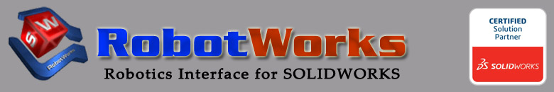
The robot can now be selected from a list, with
immediate sizing verification. Each click on a robot name
shows the selected robot and limits, and each path point
appears in appropriate color for instant verification.
The internal Kinematics function will calculate all the path
points and enable perfect match for a robot.
Non-experts can rely on RobotWorks
to assure correct operation. Green light means ?go ahead, the
path is ready?.
Unlike before, there is no need to run to get joint angles.
Once the green light is on, a robot file may be saved
immediately (perfect for long jobs with small changes).
2. Robot Selection
It is not required anymore to have any robot in the
application assembly in order to produce a path. The minimum
components are a part and a tool. The robot is
only selected after the path can be verified for reach.
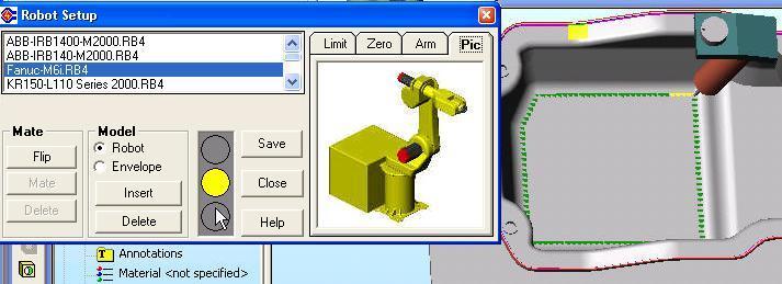
In addition to be able to see which points are reachable, and
before inserting a robot, the robot 3D envelope can be
inserted and observed, as a transparent sphere representing
the robot reach. In addition, the robot picture and limits can
be seen for verification before the robot is added.
All the robots are supplied in the new
RobotWorks 4 format, in a
special folder. (They may be used with older versions too).
Once a robot is selected it may be inserted automatically
into the assembly. In this case the original robot model (as
supplied with RobotWorks) will
remain intact and may be used again for other assemblies.
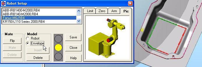
In addition to selecting robots it is now possible to
set a preferred Arm Configuration, to be used by
RobotWorks Kinematics during the
path creation.
During the path motion, if the arm configuration may
switch to the "other" solution, RobotWorks will "look
backwards" and apply the correct configuration, thus avoiding
"config change" errors later at the robot.
RobotWorks supports the idea of
the main three configuration cases Above/Below,
Up/Down and Flip/No Flip. Although different robot
controllers call these cases by different names, they still
function the same.
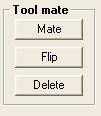
3. Automatic Tool Mounting
 Tools
(and parts in Part Mode) can now be "mounted"
automatically on the robot flange. Tools
(and parts in Part Mode) can now be "mounted"
automatically on the robot flange.
When robots are changed the tool will remain in the assembly
and be mounted automatically on the newly inserted robot.
 A
tool may now be built (or imported) in any way or
orientation. Each tool now needs a mounting flange just
like a real tool. Additional markers on the tool at the
flange will make it understood to
RobotWorks. A
tool may now be built (or imported) in any way or
orientation. Each tool now needs a mounting flange just
like a real tool. Additional markers on the tool at the
flange will make it understood to
RobotWorks.
RobotWorks now includes a
utility that creates all these attributes automatically.
All the tools used in
RobotWorks 4 will have identical interface to the
flange, so switching robots and tools will be simple and
almost automatic.
The process of mounting a tool/part to the robot
creates mates in the assembly automatically. These
mates are different than the ones used in previous versions.
4. Job Management
It is now possible to create, save and load different
jobs per one assembly. It is also possible to load a
RobotWorks job first, as it will
load the appropriate assembly used with it.
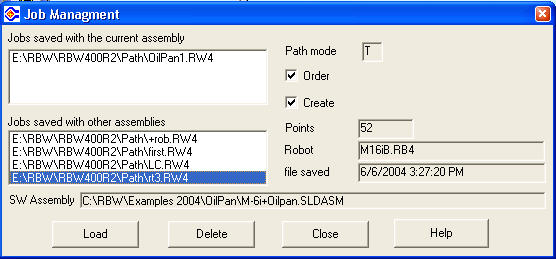
A job preview is now available, showing the
important details of a job and enables selecting the correct
one.
5. Points Reduction
New control functions reduces the number of points
automatically, based on the curvature of the path.
By default, straight lines will get only end points,
true arcs will get end points and one mid point and any
3D curve will be examined automatically and be converted to a
set of straight segments, based on user-defined distance in
3D between each point and the original curve.
This picture shows a path with 183 points, evenly spaced every
10 mm.
This picture shows the same path after points reduction,
having only 44 points, based on a maximum of 1 mm deviation
from the original curve.
This operation may be repeated as necessary.
6. Process vs. Simulation Points
 A
new approach is now taken to differentiate between "what
you see" (on the screen during simulation) and "what
you get" (at the robot). A
new approach is now taken to differentiate between "what
you see" (on the screen during simulation) and "what
you get" (at the robot).
Robots will move between points in straight line even when
given only two points. However,
RobotWorks must run along many mid-points just
to make the simulation look realistic.
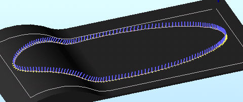
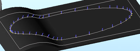
Therefore, the path points are now having two types,
those used for simulation and collision detection (many
points in fine pitch) called Motion points (shown here
as yellow lines), and those used to be exported to the
robot (called Process points, shown here as blue
squares).
The division follows the Reduce Points concept.
For example, a square will only send 4 points to the robot,
but may have hundreds of points for the realistic simulation
and ability to check collision between points.
In addition, along true arcs or circles, although few points
will be sent to the robot, the motion on the screen will
still be shown circular.
All the points will be saved and loaded, and their duty
may be switched by the user at any point.
7. Points Access in the Path Manager
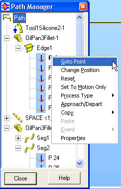 Another
concept change is the new Path Manager, which now shows and
enable access to individual path points. Another
concept change is the new Path Manager, which now shows and
enable access to individual path points.
Each lead will now show its points, numbered sequentially.
Right-click on a point enables point operation, such as:
 Goto (makes the tool jump to the point)
Reset point (resets all point modifications)
Set to Motion Only (sets point as available for
the simulation only)
Process Type (gives the user the option to add
attributes to this point)
Approach/Depart (enables approach or depart to
each point at user-defined height along Tool Z)
Copy / Paste (enables transferring point settings
to another point or group of points)
Events can be added and edited
Properties of the point can be observed.
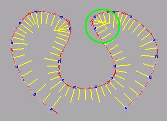
Each point will have a graphical display showing
its status so it will be easy to see modified point (like P16
shown) or points with special status.
The menu of options per point will reflect the current point
status.
8. Points Process Types
In an effort to enable better integration between
RobotWorks and actual robot jobs,
RobotWorks now assigns a
Process Type code to points, based upon what they actually
do in the robot application. The simplest form of this
definition was always internal in
RobotWorks, like the difference between point in air
to point on part. This enabled
RobotWorks, for example, to write different speed
values to points, or assign the correct motion command J
or L to the move, based on what the point is on.
This idea is now being expanded significantly, and at the same
time is open for the user to interact with.
RobotWorks now exposes this
information to the Convert grid and gives the user a
way to view and modify it to better suit the
application.
All RobotWorks'
post-processors now take their input from the grid
without "internal" decision what is "right" or "wrong".
Users now have much better control on what the robot will
receive.
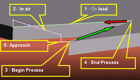
The assigned process types are as follows:
1. Point on lead - The point is on a part,
in middle of a process (e.g. during welding, gluing etc.)
2. Point in air - On spaces, Pose points or on its way
to or from other process points of any type.
3. Begin Process - The first process point on a
lead (where usually a process is switched on, e.g. ARC ON)
4. End Process - The last process point on lead
(where usually a process is switched off, e.g. ARC OFF)
5. Approach Point - A point before the
first process point on lead (sometimes used to start
process in air)
6. Depart Point - A point after the last
process point on lead (sometimes used to stop process in air)
Process types are assigned automatically by
RobotWorks to every process
point (a point exported to the robot), but the user can change
the type easily at any point.
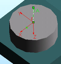
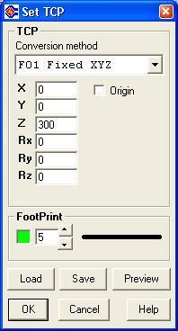
9. TCP Settings
TCP is a robotics concept (Tool Center
Point) and is now embedded in
RobotWorks too, as an effort to make things more
like in robotics and less like in CAD.
Prior to this version, RobotWorks
used to move the tool /part based upon its origin point as
set in SOLIDWORKS. Tools had
to be built in one special way, with their TCP at the
origin and also oriented in special way (Z out etc.).
The tool now works just like in a robot - if no tool is
selected, the point of reference is the flange center.
Setting the TCP in RobotWorks is
now identical to the way it's done on the robot, and the
same numbers may be entered (e.g. if a tool was defined at
the robot using a teach pendant).
TCP settings may be saved and loaded, so the
same tool may be used with several settings to check "what if"
easily.
The tool now may leave behind a visible Footprints in
user-defined color and width, to enable seeing where the robot
has already been.
10. Save and Load Points and Paths
In previous versions RobotWorks
saved only modified points, and upon loading it
reconstructed the Order of selections and Created
new points based on the selections.
In this version, all the points are saved (simulation
and process points) and loaded. If the path can be
reconstructed, the Script will load as before and all
the original points will be re-instated.
A built-in internal converter will load RW3 files and upgrade
their data automatically. If leads will not match the current
assembly, the available points will still be loaded (as
External type) and become regular points.
There will be a wizard assisting the users to upgrade
some parts in the assembly in order for them to be compatible
with RobotWorks 4.
11. Instant Update upon Point
Modifications
All point modifications except pitch change will
act transparently and immediately without Create again.
That will include approach / depart, takeoff / landing,
offsets etc.
motion within an
envelope of about 2 x 2 x 2 meters, with accuracy of few
mm / degrees.
Records the motion (location and orientation) and the
finger activity (trigger). Optionally records analog
finger position.
Different tips / tools may be mounted on the pod (the
movable handle). |