|
Not all parts are born equal
Your part geometry will usually dictate most of the path.
However, the robot tool may be far away from the part or the
worktable. What do we do with the spaces between faces?
We create guide parts. Unlike other parts in the assembly,
there is no need to produce them, or to make a dimensioned
drawing for them. They are in the assembly merely in order to
have the robot tool ride on their back.
You make them from a simple sketch, extruded, swept or lofted,
and mate them to real parts (designed or imported) to create a
complete path. If you do not create any guide parts, the
program will create straight-line motions between the parts
for you.
What about the robot tool? Well, it is a SOLIDWORKS part too!
You can design it from scratch or maybe get it from the
manufacturer drawings.
And what about the robot, you keep asking? The robot itself is
a SOLIDWORKS assembly with mates defining its joints. You can
move its joints to your liking to perform a reach study, see
collisions, mate different tools to it and 'crash' it all you
like. It is cheaper when it only happens on the screen.
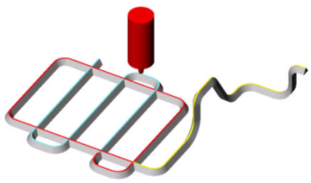
The above is an application example: laser cutting of a plate
into four strips.
A sketch with a simple triangle, using sweep, with the tool
riding a chamfer on top, makes the path parts.
The 'real' parts are the ones with the blue and red chamfers,
representing the three cuts across the plate and the trimming
of the plate around. The curved guide parts, swept along a 3D
sketch with the yellow chamfer, are there to steer the robot
away and above an obstacle on the table, to avoid collision.
It is hard to tell which part is for real and which is just to
guide, but it is unimportant anyway. The purpose is to get a
robot trajectory quickly, without the robot.
Download this
article in PDF
|