|
You've got a point
Robot controllers are very smart. They can drive a robot in
perfect interpolation (all the joints starting and stopping
together in smooth motion). You just give them points and they
will create the actual motion.
Uh, right, you just give them points...
Where do the points come from? In manual teaching, you drive
the robot and declare a point at any desired position in
space, and it is the duty of the robot controller to connect
all the points in an imaginary smooth curve.
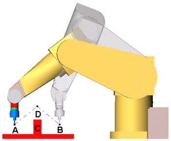
However, robot controllers have logic of their own. Left to
their own devices, the tool will move between point A and B
through object C. You should have entered a point D in mid air
above the object, but you didn't. And it's hard to blame you,
since most cases are far less obvious and 3D vision is not
common among humans.
No one can really envision each and every intermediate
position of every robot part along the way. High-end robot
simulation programs can, but not every plant is General
Motors.
Enter RobotWorks, the real power behind the path.
Make a simple sketch from A to B through D, extrude -
finished. You saved your face, literally.
Inside SOLIDWORKS the faces you picked may be very different
mathematically. Not only it is possible to create the same
face in more then one way, but solid geometry can create
strange and hard to envision faces (think of face blend or
loft with guide curves...). Moreover, during your design you
change parts position and orientation, add or edit parts, and
may end up looking at an assembly that does not resemble a
path at all.
RobotWorks internal algorithms take care of all that for you.
Not only does it connect all the faces into one long path; it
also applies points evenly along the faces. You set a pitch
(distance between points) to each part, feature or face, or
use default one for the whole path. Every point is calculated
according to the feature it is on and then saved with the
related location and orientation data.
Download this
article in PDF
|